Understanding the Importance of Solar Panel Wiring Diagrams
A schematic solar panel wiring diagram is a visual guide that illustrates the connections and components of a solar power system. It helps in planning, installing, and troubleshooting solar setups efficiently. These diagrams are essential for ensuring safety, efficiency, and compliance with electrical standards. By following a well-designed schematic, users can avoid common mistakes and optimize energy output. Whether for residential, off-grid, or RV systems, a clear wiring diagram is the foundation of a successful solar installation. It simplifies complex electrical connections, making it easier to understand how panels, inverters, and batteries interact within the system.
- Provides a clear roadmap for solar installations.
- Helps identify components and their interconnections.
- Ensures safety and efficiency in solar power systems.
Understanding the Basics of Solar Panel Wiring
Solar panel wiring involves connecting photovoltaic (PV) modules, inverters, charge controllers, and batteries to form a functional solar power system. The basic principle revolves around converting sunlight into usable electricity through a structured electrical circuit. Key components include solar panels, which generate DC power, and inverters, which convert DC to AC for household use. Charge controllers regulate energy flow to batteries, ensuring efficient charging and preventing over-discharge. Proper wiring ensures safety, maximizes energy output, and minimizes losses. Understanding series and parallel connections is crucial for configuring panels to meet voltage and current requirements. Correct wire sizing and safety precautions are essential to avoid overheating and electrical hazards.
- Connects PV modules to inverters and charge controllers.
- Converts DC power to AC for usable energy.
- Ensures efficient energy storage and distribution.
Components of a Solar Panel Wiring System
A solar panel wiring system includes solar panels, inverters, charge controllers, and batteries. These components work together to generate, regulate, and store energy for efficient power distribution and use;
Solar Panels, Inverters, Charge Controllers, and Batteries
Solar panels are the core of any solar power system, converting sunlight into electrical energy. Inverters are essential for converting the DC power generated by panels into usable AC power for homes and appliances. Charge controllers regulate the flow of energy between panels and batteries, preventing overcharging and ensuring efficient energy storage. Batteries store excess energy for use during periods of low sunlight or at night. Together, these components form a balanced system that optimizes energy generation, storage, and distribution. Understanding their roles and connections is crucial for designing and maintaining an efficient solar power setup.
How to Read a Schematic Diagram
Reading a schematic diagram involves identifying symbols for solar panels, inverters, and batteries. Follow the flow of energy to understand connections and system layout clearly for efficiency.
Identifying Symbols and Connections
Identifying symbols and connections in a schematic diagram is crucial for understanding the solar panel wiring system. Each component, such as solar panels, inverters, and batteries, is represented by specific symbols. These symbols are standardized, making it easier to interpret the diagram. Connections between components are shown by lines, indicating how energy flows through the system. For example, a solar panel symbol typically looks like a circle with arrows pointing inward, representing light absorption. Understanding these symbols helps in troubleshooting and ensures that the system is wired correctly. Proper identification also aids in recognizing potential points of failure and optimizing energy flow.
- Symbols represent components like panels and inverters.
- Lines indicate energy flow and connections.
- Understanding symbols aids in troubleshooting.
Design Considerations for Solar Panel Wiring
Series vs. Parallel Connections and Wire Sizing
Proper design ensures efficiency and safety. Series connections boost voltage, while parallel connections increase current. Correct wire sizing prevents energy loss and overheating, ensuring optimal performance.
- Series boosts voltage; parallel increases current.
- Wire size must match ampacity and distance.
In solar panel wiring, series connections increase voltage while parallel connections boost current. Series setups are ideal for higher voltage requirements but risk reduced output if one panel underperforms. Parallel connections provide redundancy and consistent voltage, making them suitable for varying conditions; Proper wire sizing is critical to prevent energy loss and overheating. Wire thickness must be calculated based on the system’s current and distance between components. Undersized wires can lead to inefficiency and safety hazards. Always consult local electrical codes and manufacturer guidelines for optimal design. Balancing these factors ensures a safe, efficient, and reliable solar power system.
- Series connections: Higher voltage, potential single-point failures.
- Parallel connections: Redundancy, consistent voltage output.
- Wire sizing: Crucial for efficiency and safety.
- Disconnect power before maintenance.
- Wear protective gear.
- Follow safety codes.
- Double-check all connections.
- Use the correct wire gauge.
- Test the system regularly.
- Ensure proper grounding.
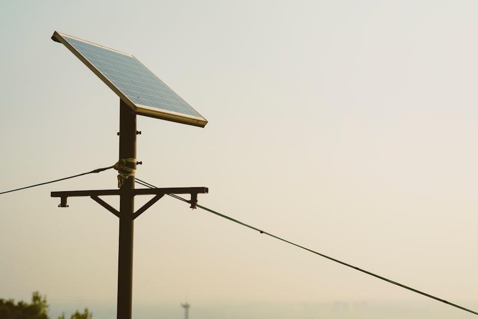
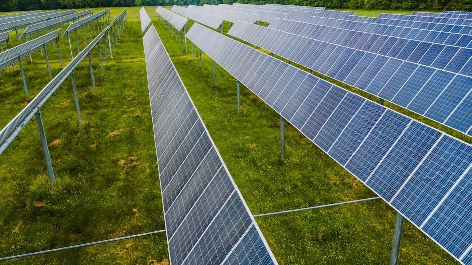
- Residential installations.
- Off-grid energy solutions.
- RV and van conversions.
- Residential systems for grid-tied and hybrid setups.
- Off-grid systems for remote energy independence.
- RV and van conversions for mobile solar power.
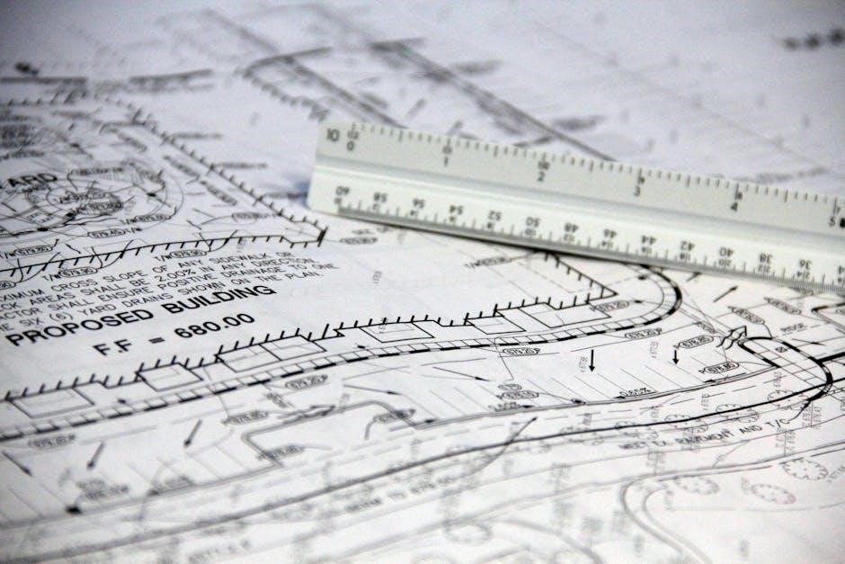
- Fritzing for DIY designs.
- Altium for advanced layouts.
- Online templates for quick starts.
- Fritzing and Altium for advanced designs.
- Explorist.life for camper and RV diagrams.
- Free tools like Inkscape for basic layouts.
- Inspect connections for tightness and corrosion.
- Use multimeters to detect voltage irregularities.
- Refer to diagrams for accurate fault tracing.
- Verify connections for tightness and corrosion.
- Use multimeters to measure voltage and detect irregularities.
- Trace connections using diagrams to identify breaks or faults.
- Check inverter error codes for specific issues.
- Ensure all components are properly grounded.
- Essential for safe and efficient solar installations.
- Facilitate troubleshooting and system optimization.
- Support renewable energy adoption and sustainability.
- Beneficial for both professionals and DIY projects.
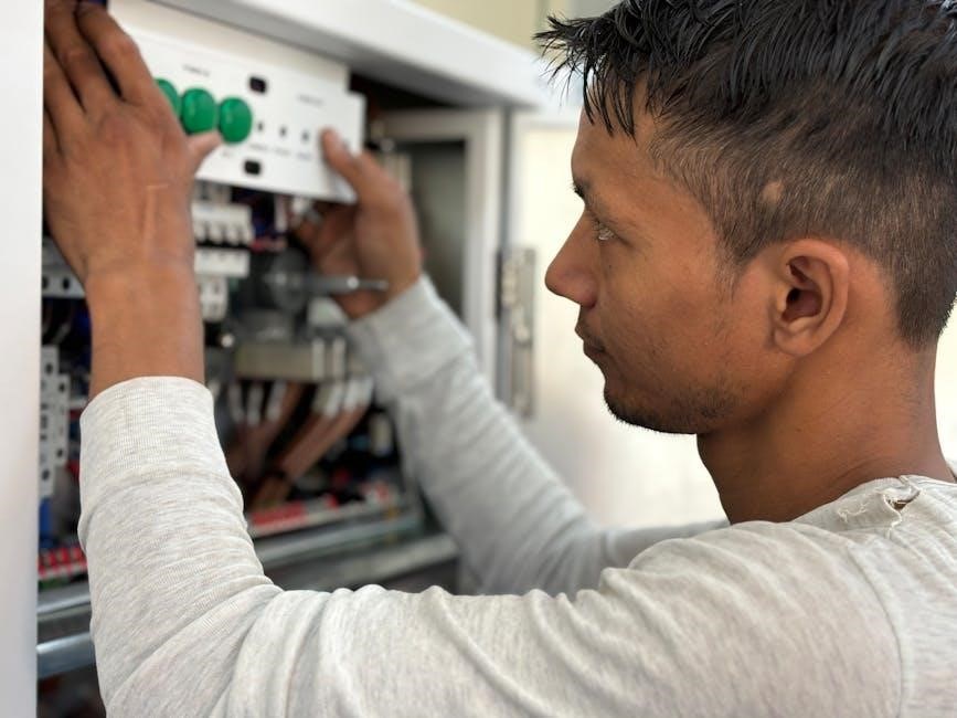
Safety Precautions and Best Practices
Always disconnect power before working on solar systems. Use protective gear like gloves and safety glasses. Follow local electrical codes and manufacturer guidelines to ensure compliance. Regularly inspect wiring and components for damage or wear. Properly ground the system to prevent shock hazards. Keep circuits labeled for easy identification. Avoid overloading circuits, and ensure all connections are secure. Regular maintenance enhances safety and system efficiency. Never attempt repairs without proper training or tools. Prioritize caution to minimize risks and ensure a reliable solar power setup.
Avoiding Common Mistakes and Ensuring System Efficiency
Common mistakes in solar wiring include incorrect series or parallel connections, improper wire sizing, and insufficient grounding. These errors can lead to reduced efficiency, overheating, or system failure. To avoid these issues, always follow the schematic diagram and double-check connections. Ensure wires are appropriately sized for the current and voltage to prevent power loss. Regularly test the system to identify faults early. Properly label all components to avoid confusion during maintenance. Grounding should be done correctly to protect against electrical shocks and surges. By adhering to best practices and consulting resources like wiring diagrams, you can ensure a safe and efficient solar power system.
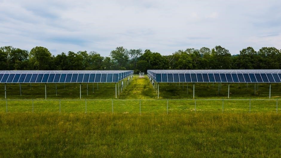
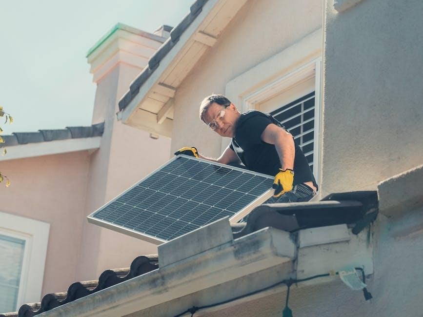
Applications of Solar Panel Wiring Diagrams
Solar panel wiring diagrams are essential for residential, off-grid, and RV solar systems. They guide installations, ensuring safe and efficient energy generation in diverse setups.
Residential, Off-Grid, and RV Solar Systems
Solar panel wiring diagrams are widely used in residential, off-grid, and RV solar systems to ensure proper installation and functionality. Residential systems often involve grid-tied setups, requiring precise wiring to integrate with existing electrical infrastructure. Off-grid systems rely on battery storage and inverters, making accurate diagrams crucial for energy independence. RV solar systems are designed for mobility, with compact configurations that maximize space and efficiency. These diagrams help users avoid common mistakes, such as incorrect wire sizing or faulty connections, ensuring safe and reliable energy generation. They also provide a clear roadmap for troubleshooting and maintenance, essential for long-term performance in diverse applications.

Tools and Resources for Creating Wiring Diagrams
Software tools like Fritzing and Altium enable users to design detailed solar panel wiring diagrams. Online platforms offer templates and tutorials for creating professional-looking schematics.
Software and Online Platforms for DIY Designs
DIY enthusiasts can utilize software like Fritzing and Altium to create detailed solar wiring diagrams. These tools offer libraries of electrical components and intuitive interfaces for custom designs. Online platforms such as Explorist.life provide pre-made templates and tutorials for solar panel wiring, catering to campers, vans, and RVs. Additionally, websites like AllData offer comprehensive resources, though some may require a subscription. For beginners, free tools like Inkscape or even Microsoft Visio can be used to draft basic schematics. These resources empower users to design safe and efficient solar systems, ensuring their projects are well-planned and functional.
Troubleshooting Common Issues
Identifying and Fixing Faults in Solar Panel Wiring
Solar panel wiring issues often stem from faulty connections or incorrect configurations. Use diagrams to trace connections, check for loose wires, and ensure proper polarity. Tools like multimeters can help identify voltage drops or ground faults. Regular inspections and adherence to safety protocols minimize risks and optimize system performance. Addressing these issues promptly prevents long-term damage and ensures reliable energy generation. Always refer to the schematic for guidance during troubleshooting to pinpoint and resolve problems efficiently.
Troubleshooting solar panel wiring involves systematic inspection using schematic diagrams to locate faults. Start by verifying all connections for tightness and corrosion, as these are common issues. Use a multimeter to check voltage levels across panels and inverters, ensuring readings match the diagram’s specifications. Ground faults or open circuits can cause system malfunctions, so inspect each component’s wiring. If a panel isn’t producing power, refer to the diagram to trace its connection and identify potential breaks. For inverters, check error codes and ensure proper configuration. Addressing faults promptly prevents energy loss and extends system lifespan. Always follow safety protocols when handling electrical components to avoid risks.